Tube Radio Australia..
--------------------------------------------------------------------------------
The DCTL Antenna
Thanks To ARNIE CORO
Host of "Dxers Unlimited"
SEND YOUR COMMENTS, QUESTIONS AND IDEAS DIRECTLY TO Him AT: arnie@radiohc.org
--------------------------------------------------------------------------------
The DCTL was developed by Jim McLelland, WA6QBU, and was published in CQ
and 73 Magazines in mid and late 1994. The construction material is simply
300 ohm heavy duty TV twinlead. (Dimensions here are for the 80m version,
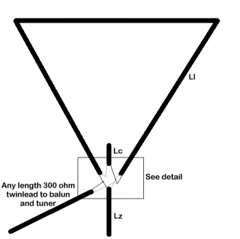
tables and formulas follow at the end.) 80 meter example: Using a 28' length
of twinlead, the opposite wires are connected to a shorted 4' 6" stub of
300 ohm twinlead. The remaining two ends of the 28' twinlead connects to
an open capacitive stub, 30" in length, also made of 300 ohm twinlead. Let's
save a couple of thousand words and see a picture:


Now this gives you an overall picture of the antenna. Lz has a shorted end,
while Lc is left open on the non-connected end. The critical part is in the
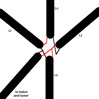
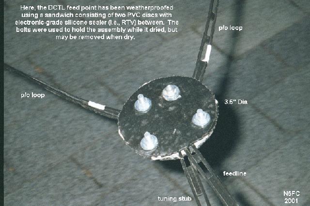
connections. Each "side" of twinlead is in a different color, and the connections
are shown below. The Ll (large loop) connection , properly made, puts a "twist"
in the twinlead of 1/2 turn. These diagrams assume that NO twisting is made
in the twinlead, and what the resulting connections look like. Use an ohmmeter
to ensure you are NOT connecting the same wires! Use heat shrink or other
GOOD insulating material -- the voltages and heat can get very very high
at the junction points. Good soldered connections are also critical.
Here is the detail of the connections:

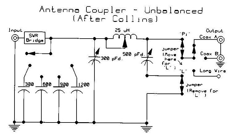
Why, if the antenna is resonant, is a tuner required? Well, it's not. But
your usable bandwidth (2:1 swr points) is pretty narrow, at 1/100th of the
design frequency. So, adding a tuner stretches it out a bit, in a fairly
reasonable fashion. I have had no trouble with a Kenwood AT-50 in covering
the entire 40 meter band. If your tuner requires a 50 ohm coaxial input (like
mine does) you can use a 6:1 balun in line.
Trimming the open capacitive stub 6" will raise the resonance point approximately
100 kHz for 80/75 meters.
Here are the formulas:
The total length (Ll and Lz, or Lt) = 130 / F(MHz)
The shorted stub (Lz) = 27 / [(2xF(MHz))-2]
Loop length (Ll) = Lt-Lz
Capacitive tuning stub (Lc) = 24 x (1 / [F(MHz)/2]**2)
(Note: Capacitive stub becomes pretty useless above 30m, in fact the whole
antenna gets pretty darn small!)
Remember, adding the capacitive stub lowers the resonant frequency!
Play around with it. EXPERIMENT WITH IT!!! I have a portable one on 40m,
and I love it, ESPECIALLY DURING THE HURRICANE SEASON.
Here are some pre-calculated dimensions. Remember that the total loop length
can be divided by three (in a delta configuration) or four (in a square configuration)
to give you an idea on space required. The square configuration tends to
be slightly more efficient, and as a matter of fact, making the antenna a
circular loop provides the maximum possible efficiency.
Band
Freq.
Lt
Lz
Ll
Lc (to lower resonant freq. by 100 kHz)
160 meter band
Freq= 2.0
Lt= 65' 0"
Lz= 13' 6"
LI= 51' 6"
Lc= 24"
75 meter band
Freq= 3.8 mHz
Lt= 33' 6"
Lz= 4' 6"
LI= 28' 0"
Lc= 6"
40 meter band
Freq= 7.1
Lt= 18'
Lz= 2' 2"
LI= 15' 8"
Lc= 1 3/8"
30 meter band
Freq= 10.1
Lt= 13'
Lz= 1' 6"
LI= 11' 4"
Lc= 1"
20 meter band
Freq= 14.1
Lt= 9' 6"
Lz= 1' 0"
LI= 8'
Lc= 1/2"
The antenna becomes hard to tune up on the 17, 15, 12 and 10 meter bands,
because it becomes rather small in size, making the dimensions much more
critical.
This is a SINGLE BAND ANTENNA, intended to make possible amateur radio transmissions
for those that can not install any other type of antenna system. It does
work indoors, when properly re-tuned in order to consider the proximity of
nearby objects. An antenna tuner is essential, and if yours is not a balanced
antenna tuner then a 6 to 1 balun MUST BE USED in case your tuner has a 50
ohms input. BUT, you can get away with a simpler, easier to make 4 to 1 balun!!!


